TM-9-2320-272-23-4 - Page 1159 of 1393
INSTALLATION
1.
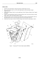
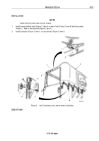
Insert PTO control cable (Figure 3, Item 9) through hole in firewall (Figure 3, Item 15).
2.
Place grommet (Figure 3, Item 11) on PTO control cable (Figure 3, Item 9) and install on firewall
(Figure 3, Item 15).
3.
Install cable clevis (Figure 3, Item 5) on control cable (Figure 3, Item 9). Tighten nut (Figure 3, Item 7) against
cable clevis.
4.
Install PTO control cable (Figure 3, Item 9) on control lever (Figure 3, Item 1) with clevis pin (Figure 3, Item 8),
washer (Figure 3, Item 4), and cotter pin (Figure 3, Item 2).
5.
Install spacer (Figure 3, Item 12) and PTO control cable (Figure 3, Item 9) on shift panel (Figure 3, Item 16)
with clamp (Figure 3, Item 13), two screws (Figure 3, Item 14), and nuts (Figure 3, Item 10).
6.
Install access cover (Figure 3, Item 6) on shift panel (Figure 3, Item 16) with six screws (Figure 3, Item 3).
M6110DAA
6
7
8
9
10
11
12
13
14
15
16
5
4
3
2
1
Figure 3.
Transmission PTO Control Cable Installation (M939A2).
TM 9-2320-272-23-4
0730
0730-4
Back to Top


