TM-9-2320-272-23-4 - Page 1152 of 1393
REMOVAL - Continued
NOTE
Tag all ends of PTO cable for installation.
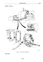
5.
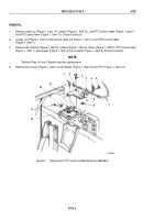
Remove six screws (Figure 2, Item 9) and access cover (Figure 2, Item 8) from PTO control panel
(Figure 2, Item 15).
6.
Remove two locknuts (Figure 2, Item 7), screws (Figure 2, Item 2), clamp (Figure 2, Item 6), and spacer
(Figure 2, Item 5) from PTO control panel (Figure 2, Item 15). Discard locknuts.
7.
Remove cotter pin (Figure 2, Item 11), washer (Figure 2, Item 12), and clevis pin (Figure 2, Item 14) from PTO
control lever (Figure 2, Item 1), and pull end of control cable (Figure 2, Item 4) clear of PTO control panel
(Figure 2, Item 15). Discard cotter pin.
8.
Loosen nut (Figure 2, Item 10) on PTO control cable (Figure 2, Item 4) and remove cable clevis
(Figure 2, Item 13).
9.
Pull PTO control cable (Figure 2, Item 4) on PTO control panel (Figure 2, Item 15) through grommet
(Figure 2, Item 3) and into cab.
M9788DAA
6
7
8
9
10
11
12
13
14
15
5
4
3
2
1
Figure 2.
Transmission Control Cable Removal.
END OF TASK
TM 9-2320-272-23-4
0729
0729-3
Back to Top

