TM-9-2320-272-23-4 - Page 301 of 1393
DISASSEMBLY - Continued
4.
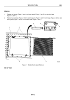
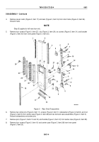
Remove seven rivets (Figure 3, Item 17) and seal (Figure 3, Item 16) from door frame (Figure 3, Item 26).
Discard rivets.
NOTE
Step (5) applies to left rear door only.
5.
Remove four screws (Figure 3, Item 27), clip (Figure 3, Item 29), six screws (Figure 3, Item 31), and bracket
(Figure 3, Item 30) from inner panel (Figure 3, Item 25).
3
4
5
M3038DAA
1
2
6
7
8
9
10
11
12
13
14
11
7
9
8
6
5
4
32
31
30
29
28
27
26
25
15
16
17
18
19
20
21
22
23
24
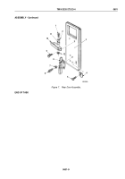
Figure 3.
Rear Door Disassembly.
6.
Remove two cotter pins (Figure 3, Item 11), screws (Figure 3, Item 7), lockwashers (Figure 3, Item 8), and rod
(Figure 3, Item 9) from center case (Figure 3, Item 28) and two bolt and case assemblies (Figure 3, Item 5).
Discard lockwashers and cotter pins.
7.
Remove pins (Figure 3, Items 13 and 14) and handle (Figure 3, Item 12) from center case (Figure 3, Item 28).
8.
Remove four screws (Figure 3, Item 10) and center case (Figure 3, Item 28) from inner panel
(Figure 3, Item 25).
TM 9-2320-272-23-4
0601
0601-4
Back to Top


