TM-9-2320-272-23-4 - Page 387 of 1393
REMOVAL
1.
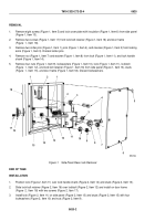
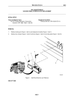
Remove eight screws (Figure 1, Item 5) and lock cover plate with insulation (Figure 1, Item 6) from side panel
(Figure 1, Item 13).
2.
Remove two screws (Figure 1, Item 17) from lock bolt retainer (Figure 1, Item 16) and door frame
(Figure
1,
Item
18).
3.
Remove two cotter pins (Figure 1, Item 1), pins (Figure 1, Item 4), and clevises (Figure 1, Item 2) from locking
arms (Figure 1, Item 3). Discard cotter pins.
4.
Remove nut (Figure 1, Item 7) and washer (Figure 1, Item 8) from lock (Figure 1, Item 11), and lock handle
shank (Figure 1, Item 14).
5.
Remove four nuts (Figure 1, Item 9), lockwashers (Figure 1, Item 10), lock (Figure 1, Item 11), lockbolt
(Figure
1,
Item
12), and lock bolt retainer (Figure 1, Item 16) from side panel (Figure 1, Item 13), studs
(Figure
1,
Item
15), and door frame (Figure 1, Item 18). Discard lockwashers.
M5347DAA
5
6
4
3
2
1
2
1
18
17
16
15
14
13
12
11
10
8
7
3
9
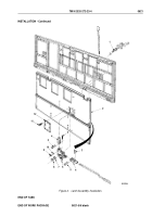
Figure 1.
Side Panel Rear Lock Removal.
END OF TASK
INSTALLATION
1.
Position lock (Figure 2, Item 11) over lock handle shank (Figure 2, Item 14) and studs (Figure 2, Item 15).
2.
Slide lock bolt retainer (Figure 2, Item 16) over lockbolt (Figure 2, Item 12) and install on door frame
(Figure
2,
Item
18) with two screws (Figure 2, Item 17).
3.
Install lock (Figure 2, Item 11) on side panel (Figure 2, Item 13) and studs (Figure 2, Item 15) with four
lockwashers (Figure 2, Item 10) and nuts (Figure 2, Item 9).
TM 9-2320-272-23-4
0620
0620-2
Back to Top


