TM-9-2320-272-23-4 - Page 405 of 1393
REMOVAL
1.
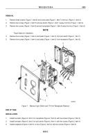
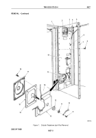
Remove three screws (Figure 1, Item 8) and cover plate (Figure 1, Item 7) from box (Figure 1, Item 2).
2.
Remove two screws (Figure 1, Item 9) and pull switch (Figure 1, Item 1) away from box (Figure 1, Item 2).
3.
Remove two screws (Figure 1, Item 6) and pull receptacle (Figure 1, Item 5) away from box (Figure 1, Item 2).
NOTE
Tag all leads for installation.
4.
Remove five screws (Figure 1, Item 4) and leads (Figure 1, Item 3) from pull switch (Figure 1, Item 1).
5.
Remove five screws (Figure 1, Item 4) and leads (Figure 1, Item 3) from receptacle (Figure 1, Item 5).
3
4
5
M9925DAA
1
9
2
3
3
6
7
8
Figure 1.
Blackout Light Switch and 110-Volt Receptacle Removal.
END OF TASK
INSTALLATION
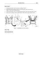
1.
Install five leads (Figure 2, Item 3) on receptacle (Figure 2, Item 5) with five screws (Figure 2, Item 4).
2.
Install five leads (Figure 2, Item 3) on pull switch (Figure 2, Item 1) with five screws (Figure 2, Item 4).
3.
Install receptacle (Figure 2, Item 5) on box (Figure 2, Item 2) with two screws (Figure 2, Item 6).
TM 9-2320-272-23-4
0625
0625-2
Back to Top


