TM-9-2320-272-23-4 - Page 406 of 1393
INSTALLATION - Continued
4.
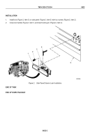
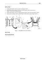
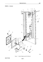
Install pull switch (Figure 2, Item 1) on box (Figure 2, Item 2) with two screws (Figure 2, Item 9).
5.
Install cover plate (Figure 2, Item 7) on box (Figure 2, Item 2) with three screws (Figure 2, Item 8).
3
4
5
M9926DAA
1
9
2
3
3
6
7
8
Figure 2.
Blackout Light Switch and 110-Volt Receptacle Installation.
END OF TASK
FOLLOW-ON MAINTENANCE
Connect auxiliary A/C power source and check operation of light switch and 110-volt receptacle.
(TM
9-2320-272-10)
END OF TASK
END OF WORK PACKAGE
TM 9-2320-272-23-4
0625
0625-3/4 blank
Back to Top

