TM-9-2320-272-23-4 - Page 749 of 1393
INSTALLATION - Continued
13.
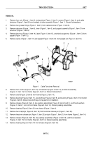
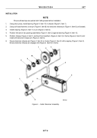
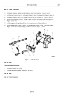
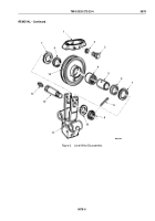
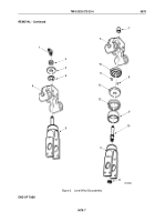
Install lever (Figure 6, Item 6) on shaft (Figure 6, Item 5) with setscrew (Figure 6, Item 7).
14.
Install spring (Figure 6, Item 12) and poppet (Figure 6, Item 13) in poppet nut (Figure 6, Item 14).
15.
Install latch (Figure 6, Item 11) on poppet (Figure 6, Item 13) with latch nut (Figure 6, Item 15).
16.
Install poppet assembly (Figure 6, Item 8) in lever (Figure 6, Item 5) and install with poppet nut
(Figure
6,
Item
14).
17.
Install two grease fittings (Figure 6, Item 10) on cable tensioner (Figure 6, Item 9).
18.
Install cable tensioner (Figure 6, Item 9) on roller assembly (Figure 6, Item 1) with four screws
(Figure
6,
Item
4), lockwashers (Figure 6, Item 3), and nuts (Figure 6, Item 2).
M6005DAA
15
7
6
5
14
11
12
13
9
10
1
2
3
4
8
Figure 6.
Cable Tensioner.
END OF TASK
FOLLOW-ON MAINTENANCE
1.
Install winch cable. (WP
0674)
2.
Lubricate tensioner assembly. (Volume 5, WP
0820)
END OF TASK
END OF WORK PACKAGE
TM 9-2320-272-23-4
0677
0677-8
Back to Top

