TM-9-2320-272-23-4 - Page 907 of 1393
ASSEMBLY - Continued
23.
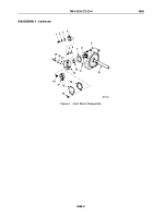
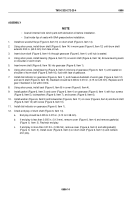
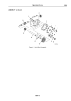
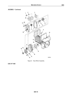
Install seal (Figure 8, Item 18) and bearing (Figure 8, Item 17) on housing (Figure 8, Item 12).
24.
Install gasket (Figure 8, Item 11) and housing (Figure 8, Item 12) on gearcase (Figure 8, Item 10) with four
lockwashers (Figure 8, Item 13) and screws (Figure 8, Item 14).
25.
Install woodruff key (Figure 8, Item 9) in worm shaft (Figure 8, Item 19).
26.
Using puller, install drive gear (Figure 8, Item 16) on worm shaft (Figure 8, Item 19).
27.
Install snapring (Figure 8, Item 15) on worm shaft (Figure 8, Item 19).
28.
Install input shaft gear (Figure 8, Item 4) on input shaft (Figure 8, Item 6).
29.
Install input shaft (Figure 8, Item 6) and input shaft gear (Figure 8, Item 4) on housing (Figure 8, Item 12).
30.
Install bearing (Figure 8, Item 8) on cover (Figure 8, Item 20).
31.
Install gasket (Figure 8, Item 7) and cover (Figure 8, Item 20) on housing (Figure 8, Item 12) with ten
lockwashers (Figure 8, Item 22) and screws (Figure 8, Item 21).
32.
Install woodruff key (Figure 8, Item 5) in input shaft (Figure 8, Item 6).
33.
Install gasket (Figure 8, Item 3) and adapter (Figure 8, Item 23) on cover (Figure 8, Item 20) with four
lockwashers (Figure 8, Item 2) and screws (Figure 8, Item 1).
TM 9-2320-272-23-4
0696
0696-18
Back to Top

