TM-9-2320-272-23-5 - Page 104 of 623
INSTALLATION - Continued
CAUTION
U-bolts and pins installed in Steps (18) through (22) must be aligned before tightening. Do
not over-tighten or damage to cab will result.
29.
Tighten all screws and nuts that remain loosely installed from Steps (2) through (19).
30.
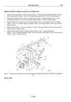
Install four ammo tray supports (Figure 28, Item 12) and ammo box tray (Figure 28, Item 10) on left and right
front sides of support assembly (Figure 28, Item 11) with eight washers (Figure 28, Item 1), screws
(Figure
28,
Item
2), washers (Figure 28, Item 9), and locknuts (Figure 28, Item 8). Do not tighten locknuts.
31.
Install four braces (Figure 28, Item 5) to support assembly (Figure 28, Item 11) with four washers
(Figure
28,
Item
4), screws (Figure 28, Item 3), washers (Figure 28, Item 6), and locknuts
(Figure
28,
Item
7). Do not tighten locknuts.
32.
Tighten locknuts (Figure 28, Items 7 and 8).
33.
Tighten locknuts (Figure 16, Item 6), installed in Assembly, Step (15), connecting four ammo tray supports
(Figure 28, Item 12) and four braces (Figure 28, Item 5) to two ammo box trays (Figure 28, Item 10).
M6318DAA
7
8
9
10
11
12
1
2
3
4
5
6
Figure 28.
Lightweight Weapon Station Installation.
END OF TASK
TM 9-2320-272-23-5
0775
0775-41
Back to Top


