TM-9-2320-272-23-5 - Page 154 of 623
INSTALLATION - Continued
3.
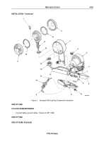
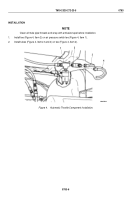
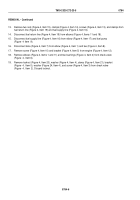
Install bushing (Figure 5, Item 4), throttle lever (Figure 5, Item 5), and bushing (Figure 5, Item 4) on bellcrank
link (Figure 5, Item 6).
4.
Install bellcrank link (Figure 5, Item 6) and throttle shaft (Figure 5, Item 9) on throttle bracket
(Figure
5,
Item
1) with washer (Figure 5, Item 2) and cotter pin (Figure 5, Item 3).
5.
Install accelerator pedal pushrod (Figure 5, Item 10) on bellcrank link (Figure 5, Item 6) with washer
(Figure
5, Item 7) and cotter pin (Figure 5, Item 8).
3
4
5
M10040DAA
1
2
6
7
8
9
10
6
Figure 5.
Automatic Throttle Component Installation.
TM 9-2320-272-23-5
0783
0783-7
Back to Top


