TM-9-2320-272-23-5 - Page 155 of 623
INSTALLATION - Continued
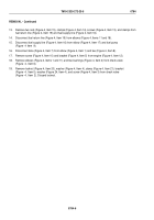
6.
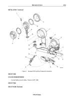
Install elbow (Figure 6, Item 3), jamnut (Figure 6, Item 4), and clevis (Figure 6, Item 5) on air cylinder
(Figure
6, Item 2). Tighten jamnut a distance of 0.25 in (6.35 mm) from air cylinder on air cylinder stud
(Figure
6,
Item
1).
3
4
5
M6281DAA
1
2
0.25 IN.
(6.35 MM)
Figure 6.
Automatic Throttle Component Installation.
NOTE
Assistant will help with Step (7).
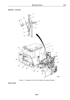
7.
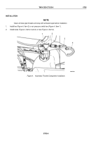
Install bracket (Figure 7, Item 5) on cab floor (Figure 7, Item 6) with four washers (Figure 7, Item 3) and screws
(Figure 7, Item 2).
8.
Install air cylinder (Figure 7, Item 1) on bracket (Figure 7, Item 5) with pin (Figure 7, Item 4), washer
(Figure
7, Item 8), and cotter pin (Figure 7, Item 7).
9.
Install tube (Figure 7, Item 9) on elbow (Figure 7, Item 10).
10.
Install pin (Figure 7, Item 15) on throttle lever (Figure 7, Item 16) with washer (Figure 7, Item 14) and cotter
pin (Figure 7, Item 13).
TM 9-2320-272-23-5
0783
0783-8
Back to Top


