TM-9-2320-272-24-2 - Page 40 of 991
TM 9-2320-272-24-2
3-225. WHEEL BEARING ADJUSTMENT
THIS TASK COVERS:
a. Front Wheel Bearing Adjustment
b. Rear Wheel Bearing Adjustment
INITIAL SETUP:
APPLICABLE MODELS
REFERENCES (TM)
All
TM 9-2320-272- 10
TOOLS
TM 9-2320-272-24P
General mechanic’s tool kit (Appendix E, Item 1)
EQUIPMENT CONDITION
Torque wrench (Appendix E, Item 145)
Wheels chocked (TM 9-2320-272-10).
MATERIAL/PARTS
Spring brake(s) caged (TM 9-2320-272-10).
Two gaskets (Appendix D, Item 164)
Ten lockwashers (Appendix D, Item 350)
Gasket sealant (Appendix C, Item 30)
1.
2.
3.
4.
5.
6.
7.
8.
9.
10.
11.
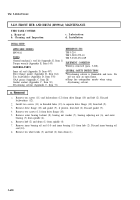
Raise vehicle until tire (1) is clear off the ground.
Remove ten screws (7) and lockwashers (6) from drive flange (5) and hub (9). Discard lockwashers (6).
Install two screws (7) into two threaded holes (8) to separate drive flange (5) from hub (9).
Remove drive flange (5) and gasket (4) from hub (9). Discard gasket (4).
Remove two screws (7) from drive flange (5).
Remove outer bearing locknut (3) and bearing nut washer (2) from spindle (11).
While rotating hub (9), tighten outer bearing adjusting nut (12) 50 lb-ft (68 N•m) to set preload.
Back outer bearing adjusting nut (12) 1/6-1/4 turn so bearing nut washer (2) can be positioned to
spindle (11) and adjusting nut insert (10).
Install bearing nut washer (2) and outer bearing locknut (3) on spindle (11). Tighten outer bearing
locknut (3) 250-400 lb-ft (339-542 N•m).
Install new gasket (4) and drive flange (5) on hub (9) with ten new lockwashers (6) and screws (7).
Tighten screws (7) 60-100 lb-ft (81-136 N•m).
Lower vehicle to ground.
3-648
Back to Top


