TM-9-2320-272-24-2 - Page 54 of 991
TM 9-2320-272-24-2
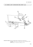
3-233. STEERING ASSIST CYLINDER MAINTENANCE
THIS TASK COVERS:
a. Removal
d. Installation
b. Disassembly
e. Travel Adjustment
c. Assembly
INlTlAL SETUP:
APPLICABLE MODELS
All
TOOLS
General mechanic’s tool kit (Appendix E. Item 1)
Torque wrench (Appendix E, Item 146)
MATERIALS/PARTS
Two cotter pins (Appendix D, Item 49)
One cotter pin (Appendix D, Item 85)
Cap and plug set (Appendix C, Item 14)
REFERENCES (TM)
TM 9-2320-272-10
TM 9-2320-272-24P
EQUIPMENT CONDITION
• Parking brake set (TM 9-2320-272-10).
• Steering assist cylinder stone shield removed
(para. 3-231).
GENERAL SAFETY INSTRUCTIONS
Do not start vehicle when steering hoses are
disconnected.
WARNING
Do not start engine when steering hoses are disconnected.
Pressure may whip hoses, causing injury to personnel.
CAUTION
Cap or plug all openings immediately after disconnecting
hydraulic lines and hoses to prevent contamination. Failure to do
so may result in steering system damage.
NOTE
• Have container ready to catch hydraulic oil.
• Tag all lines and hoses for installation.
1.
Disconnect return hoses (4) and (5) from elbows (6).
2.
Remove two grease fittings (2) from steering assist cylinder (11).
3.
Remove two cotter pins (1) from steering assist cylinder (11). Discard cotter pins (1).
4.
Loosen adjustable plugs (10) and (3), as far as possible without removing, and loosen two
dustcovers (8).
5.
Tap on adjustable plugs (10) and (3) to loosen steering assist cylinder (11) from spring shackle ball
stud (7) and steering knuckle ball stud (12).
6.
Remove steering assist cylinder (11) from ball studs (7) and (12).
7.
Remove two dustcovers (8) and felt pads (9) from ball studs (7) and (12).
8.
Remove cotter pin (13) and nut (14) from steering knuckle ball stud (12). Discard cotter pin (13).
3-642
Back to Top


