TM-9-2320-272-24-2 - Page 788 of 991
4-9. ENGINE
TM 9-2320-272-24-2
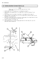
1.
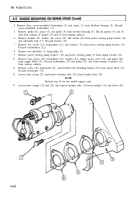
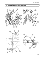
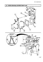
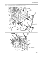
Remove screw (5), fuel return manifold (4), and banjo seal (6) from screw (3). Discard banjo
seal (6).
2.
Remove screw (3) and two washers (2) from engine block (1). Discard washers (2).
3.
Remove two screws (9), fuel transfer pump (8), fuel supply tube (7), and gasket (10) from engine
block (1). Discard gasket (10).
4.
Remove two screws (14), washers (15), power steering pump (13), and gasket (12) from air
compressor (11). Discard gasket (12).
5.
Remove oil sampling valve (19) from engine block (1).
6.
Remove oil pressure sending unit (18) from engine block (1).
7.
Disconnect nut (23) from elbow (22) and move oil line (28) aside.
8.
Remove elbow (22) from engine block (1).
9.
Remove screw (21) from air compressor (11).
10.
Loosen two clamps (17) and remove air inlet line (20) from fitting (16) and air compressor (11).
11.
Remove screw (24) and washer (25) from air compressor (11).
12.
Remove screw (26) and bracket (27) from engine block (1).
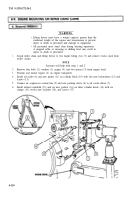
WARNING
• Lifting device must have a weight capacity greater than the
combined weight of the engine and transmission to prevent
injury or death to personnel and damage to equipment.
• All personnel must stand clear during lifting operations. A
snapped cable, or swinging or shifting load, may result in injury
or death to personnel.
• Engine must be securely mounted on repair stand. Failure to do
so may result in injury or death to personnel.
13.
Attach utility chains and suitable lifting device to two engine lifting brackets (29).
14.
Using six bolts (30), install engine block (1) on engine stand. Tighten six bolts (30) securely.
15.
Remove lifting device from two engine lifting brackets (29).
4-106
Back to Top


