TM-9-2320-272-24-3 - Page 106 of 799
TM 9-2320-272-24-3
4-62. FAN DRIVE CLUTCH (M939A2) MAINTENANCE
THIS TASK COVERS:
a.
Disassembly
b.
Cleaning and Inspection
c. Assembly
INITIAL SETUP:
APPLICABLE MODELS
M939A2
TOOLS
General mechanic’s tool kit (Appendix E, Item 1)
Micrometer (Appendix E, Item 80)
Snap gauge (Appendix E, Item 123)
Torque wench (Appendix E, Item 144)
Arbor press
Vise
MATERIALS/PARTS
Fan drive repair kit (Appendix D. Item 108)
Adhesive sealant (Appendix C, Item 4)
GAA grease (Appendix C, Item 28)
Rags (Appendix C, Item 58)
Antiseize tape (Appendix C, Item 72)
REFERENCES (TM)
TM 9-2320-272-10
TM 9-2320-272-24P
EQUIPMENT CONDITION
Fan clutch removed (para. 3-74).
GENERAL SAFETY INSTRUCTIONS
l
Return spring is under compression and may
cause injury if not properly removed.
l
When cleaning with compressed air, wear
eyeshield.
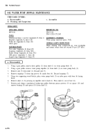
a. Disassembly
1.
2.
3.
4.
5.
6.
7.
8.
9.
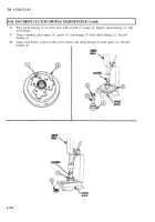
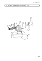
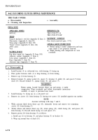
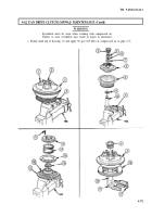
Install bracket (4) in soft-jawed vise, with housing (3) facing up.
Place prybar between studs (1) to keep housing (3) from turning.
Remove cap (2) from housing (3).
Remove locknut (5), spring washer (6), spacer (7), housing (3), pulley (8), and spacer (9) from
shaft (10). Discard locknut (5), spring washer (6), and spacer (7).
WARNING
Return spring, located between thrust cap and piston, is under
compression. Wear eyeshields and follow disassembly instructions
carefully, or injury to personnel may result.
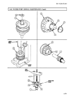
Install housing (3), facing up, in a soft-jawed vise.
Remove six screws (11) from housing (3), leaving two screws (11) installed opposite one another.
NOTE
Assistant will help with steps 7 and 8.
While assistant holds down thrust cap (12), alternately loosen and remove two remaining
screws (11) from housing (3).
Slowly release and remove thrust cap (12), return spring (13), clutch facing (14), and spacer (15)
from housing (3). Discard clutch facing (14) and spacer (15).
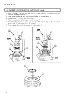
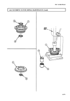
Remove piston (16) from housing (3) as follows:
a. Install cap (2) on housing (3), and place housing (3) on bracket (4).
b. Wrap rag around base of shaft (10).
4-370
Back to Top


