TM-9-2320-272-24-3 - Page 92 of 799
TM 9-2320-272-24-3
4-61. FAN DRIVE CLUTCH (M939/A1) MAINTENANCE
THIS TASK COVERS:
a. Disassembly
c. Assembly
b. Cleaning and Inspection
d. Fan Drive Clutch Operation Check
INITIAl SETUP:
APPLICABLE MODELS
M939lAl
SPECIAL TOOLS
Mandrel (Appendix E, Item 116)
Bearing replacer (Appendix E, Item 13)
TOOLS
General mechanic’s tool kit (Appendix E, Item 1)
Torque wrench (Appendix E, Item 146)
Vise
Arbor press
MATERIALS/PARTS
O-ring (Appendix D, Item 451)
Locknut (Appendix D, Item 305)
Snapring (Appendix D, Item 659)
MATERIALS/PARTS (Cod)
O-ring (Appendix D, Item 448)
O-ring (Appendix D, Item 449)
O-ring (Appendix D, Item 450)
Bearing (Appendix D, Item 11)
Two bearings (Appendix D, Item 12)
Rags (Appendix C, Item 58)
GAA grease (Appendix C, Item 28)
REFERENCES (TM)
TM 9-2320-272-10
TM 9-2320-272-24P
EQUIPMENT CONDITION
Fan drive clutch removed (para. 3-75).
GENERAL SAFETY INSTRUCTIONS
Piston spring is under compression and may cause
injury if not properly removed.
When cleaning with compressed air, wear
eyeshield.
1.
2.
3.
4.
5.
6.
7.
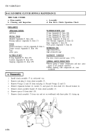
Install clutch assembly (7) in soft-jawed vise.
Remove seal plug (1) from clutch assembly (7).
Remove O-rings (2) and (31 from seal plug (1). Discard O-rings (2) and (3).
Remove expansion locknut (4). washer (5), and spacer (6) from shaft (10). Discard locknut (4).
Remove clutch assembly bracket (9) from clutch assembly (7).
Remove spacer (8) from shaft (10).
Remove clutch assembly (7) from vise and set on workbench with thrust plate (11) facing up.
4-356
Back to Top


