TM-9-2320-273-34 - Page 102 of 801
TM9-2320-273-34
(2) Install the components to the forward rear and to the rear rear axle as follows:
(a) Install the air brake chambers, if removed. (Refer to TM 9-2320-273-20.)
(b) Connect brake air lines and fittings, if removed.
(c) Install hub, drum and bearings, if removed. (Refer to TM 9-2320-273-20.)
(d) install wheels. (Refer to TM 9-2320-273-10.)
(e) Install inter axle propeller shaft. (Refer to TM 9-2320-273-20.)
NOTE
The nuts on the saddle cap studs are self-
Iocking and should be replaced once
removed.
(3) With the beams attached to the axles, roll them under the center of saddle, making sure
center bushing of each beam is lined up with center of saddle leg. Lower frame, centering saddIes on
beam center bushings. Install, but do not tighten, saddle caps, washers and nuts (fig. 2-49).
(4) Install torque rod to axle and frame brackets (TM 9-2320-273-20).
(5) Torque saddle cap nuts to 225-275 Ib-ft (305-373 N-m) making sure that equalizer
beams are level with frame.
CAUTION
Do not exceed specified torque when
tightening nut and bolt assembly.
(6) Be sure that flat section on adapter flange is in the vertical position and tighten beam
end adapter bolt nuts as follows:
(a) M915 – 210-240 Ib-ft (285-325 N-m).
(b) M916/M920 – 445-495 lb-ft (603-671 N-m).
(7) Connect propeller shaft to forward rear axle (TM 9-2320-273-20).
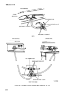
(8) Connect air lines to the tee connection and quick release valve at the rear rear axle as
tagged at removal (fig. 248).
(9) Reset spring brake at all four brake air chambers (TM 9-2320-273-20).
(10) Connect air lines to the tee connection and the quick release valve at the forward rear
axle as tagged at removal (fig. 2-47).
(11) Connect air line to forward rear axle differential lockup air chamber (fig. 2-46).
(12) Check fluid level in each axle differential and replenish if necessary (LO 9-2320-273-12).
(11) Road test vehicle and check for vibration or brake problems.
2-86
Back to Top


