TM-9-2320-273-34 - Page 405 of 801
TM 9-2320-273-34
(3)
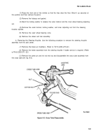
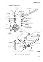
Aline the knuckle pin flats to mate with the draw key holes, and tap the knuckle pin
through the knuckle yoke: axle center and the thrust bearing from the top or bottom side.
NOTE
The draw keys are installed one from
each side of the axle center. Do not
install both keys from the same side.
Before setting the draw keys, center
the knuckle pin to equalize the gap
between the upper and lower gap
mounting surfaces.
(4)
Install the draw keys so that the flat on the key mates with the corresponding flat on
the knuckle pin.
(5)
Install the draw key nuts and torque between 30-45 Ib-ft (41-61 N·m).
d.
Knuckle Clearance (End Play) Check.
Measure the clearance between the top face of the upper
axle surface and the lower face of the knuckle pin boss as follows,
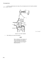
(1)
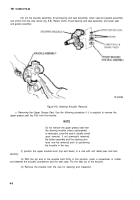
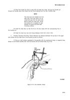
Set up a dial indicator graduated in thousandths with the mechanical clamp or magnetic base
affixed to the knuckle spindle such that the knuckle can be turned freely (fig. 9-12).
Figure 9-12. Dial Indicator Setup.
9-13
Back to Top

