TM-9-2320-273-34 - Page 408 of 801
TM 9-2320-273-34
(1)
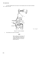
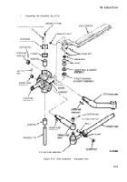
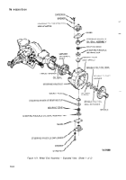
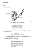
Install gaskets and steering knuckle caps at the top and bottom of the steering knuckle
bosses.
I
nstal
l
three capscrews with Iockwasher and torque 20-30 lb-ft (27-40 N·m).
(2)
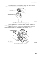
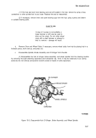
Install steering arm and ball assembly in the upper steering knuckle boss and torque nut
between 560 and 785 Ib-ft (759 and 1064 N·). Use the torque wrench to line up the cotter pin hole.
Do not back off. Install the cotter pin.
(3)
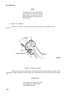
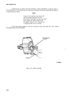
Install the cross tube arm in the lower steering knuckle boss and torque the nut between
560 and 785 Ib-ft (759 and 1064 N·m) using the torque wrench to line up the cotter pin hole. Install the
cotter pin.
(4)
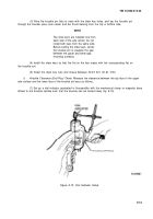
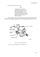
Install the cross tube assembly in the cross tube arm. Torque the tie-rod end nut between
165 and 230 Ib-ft (224 and 312 N·m) as above. Install the cotter pin.
(5)
If disassembled, the following torque values apply to the steering linkage.
(a)
Tie-rod clamp bolt: 45-55 Ib-ft (61-75 N·m)
(b)
Steering arm ball nut:
165-230 Ib-ft (224-312 N·m)
(6)
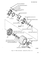
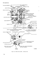
Install the wheel and hub (and brake if applicable) in reverse order of disassembly
(para 9-4a and 9-4 b).
(7)
Lubricate in accordance with LO 9-2320-273-12.
(8)
Wheel bearing adjustment procedure is contained in TM 9-2320-273-20.
9-16
Back to Top

