TM-9-2320-273-34 - Page 414 of 801
TM 9-2320-273-34
(2)
If necessary, remove expansion plug from drive flange by tapping out from the inside of the
drive flange.
(3)
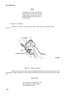
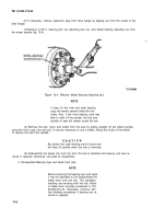
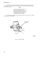
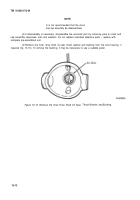
Remove 4-7/8 in. bearing jam nut, adjusting lock nut, and wheel bearing adiusting nut from
the wheel spindle (fig. 10-4).
Figure 10-4. Remove Wheel Bearing Adjusting Nut.
NOTE
In step
(4),
the inner and outer bearing
cups will remain seated inside the hub
cavity. Also, if the inner bearing cone was
able to slide off the spindle, the hub and
spindle oil seal will remain inside the hub.
(4)
Remove the hub, drum, and wheel from the axle by pulling straight off the wheel spindle,
using the tire to grip onto and pull. It may be necessary to use a mallet, hitting the inside of the wheel
to remove the hub from spindle.
CAUTIO N
Be careful; the outer bearing cone is loose and
will drop off spindle when the hub is removed.
(5)
Disassemble the wheel (rim and tire) from the hub to facilitate hub bearing and seal re-
moval, if required. Otherwise, set aside for reassembly.
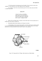
c. Disassemble Bearing Cups and Seals from Hub.
NOTE
Before removing the bearing cups and seals,
it may be desirable to first disassemble the
brake drum from the hub. This facilitates
handling and working with the hub. Refer
to brake drum removal procedures in TM
9-2320-273-20. Otherwise, continue with
the following procedures if bearing cup re-
moval is required.
10-6
Back to Top

