TM-9-2320-273-34 - Page 401 of 801
TM 9-2320-273-34
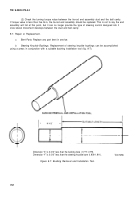
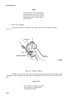
(7) Press worn bushings out of the knuckle using the small end of the bushing removal tool in
the bushing.
(2) Place a replacement bushing on the small diameter end of the tool and press it into the
steering knuckle in three steps as follows. This allows the bushing to allne itself with the bore.
(a) Press the bushing into the knuckle about 1/8 inch and then relieve pressure.
(b) Press the bushing in another 1/2 inch and relieve the pressure.
(c) press the bushing in until it is flush with the surface of the upper seal counterbore, for
the top, or with the inside surface of the lower knuckle boss for the bottom.
(d) Line ream upper and lower bushings to 1.787-1.789 in.
c. Corrosion Prevention.
Parts that have been cleaned, dried, inspected and are to be immediate-
ly reassembled should be coated with light oil to prevent corrosion. Spindles, knuckle pins or sleeves
that are to be stored for any length of time should be treated with rust preventative, wrapped in oiled
paper and boxed to keep dry and clean.
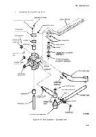
9-8. Assembly
Incorrect installation of the grease seals
could result in premature lubricant con-
tamination and a need for more frequent
lubrication and service intervals. For
maximum operating service from the
front axle assembly, install the seals by
the following procedures.
a.
Upper Grease Seal Installation.
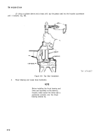
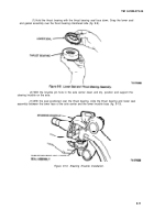
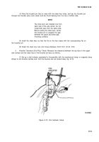
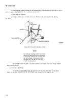
(1) place the steering knuckle, bottom side up, in a vise equipped with soft metal jaws and lock
securely.
(2) With the top end of the knuckle held firmly in this position, place the new grease seal over
the knuckle counterbore with the rubber lip facing up.
9-9
NOTE
Back to Top

