TM-9-2320-273-34 - Page 596 of 801
TM9-2320-273-34
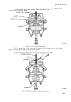
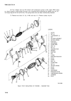
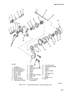
(8) Slide chamber (29) off of adapter (14).
(9) Remove diaphragm (26).
(10) Loosen nut (4) from clevis (1).
(11) Remove clevis (1) from push rod (7).
(12) Remove nut (4) from push rod (7).
NOTE
There will be a slight spring force when
the housing assembly (5) is removed.
(13) Remove two bolts (20) and nuts (22). Remove clamp (21). Lift housing assembly (5)
off of push rod (7).
(14) Disassemble return spring (6), push rod (7), and diaphragm (8).
NOTE
There will be a slight spring force when
removing screw (25) and plate (24).
(15) Remove screw (25), plate (24) and return spring (23).
(16) Remove O-ring (16) from adapter push rod (17) and slide adapter (14) off of adapter
push rod (17).
(17) Remove screw (19) and plate (18) from adapter push rod (17).
c. Cleaning and Inspection.
Wash all metal parts in dry cleaning solvent (item 12, App B). Inspect
all the parts for excessive wear or damage. Replace all parts not found in good condition. It is recom-
mended that all rubber parts be replaced.
d. Assembly.
(1) insert screw (19,
fig. 14-49) through plate (18) and install into adapter push rod (17).
Tighten securely.
(2)
(3)
(4)
.
Insert adapter push rod (17) through adapter (14).
Install O-ring (16).
Install return spring (23) over adapter push rod (17).
Change 1
14-47
Back to Top

