TM-9-2320-273-34 - Page 598 of 801
TM9-2320-273-34
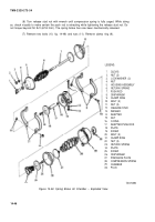
(12) Place diaphragm (26, fig. 14-49) in chamber (29).
(13) Slide chamber (29) onto adapter (14).
(14) Position the clamp ring (9) into place being careful not to misaline diaphragm (26).
(15) Install two bolts (10) and nuts (11) to retain clamp ring (9). Tighten securely.
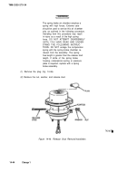
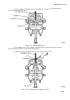
(16) Remove nut and washer (fig. 14-48).
(17) Unlock by turning counterclockwise and remove release stud from pressure plate.
(18) Install release stud into flange provided in adapter and secure with washer and nut (fig.
14-46) .
(19) Install plug.
14-16. Installation.
Refer to TM 9-2320-273-20.
14-17. Operating and Leakage Test.
NOTE
Vehicle wheels should be blocked or
vehicle held by some means other than
the vehicle brakes.
a.
Build air pressure in system to 100 psi (690 kPa) minimum; then shut down engine.
b.
Place PARK BRAKE valve in park position; air brake chambers should apply immediately.
c. Place PARK BRAKE valve in release position; air brake chambers should release immediately.
d. With the PARK BRAKE valve in the release position, apply a soap solution around the clamp
ring, and at both the drain slots and exhaust breather on the body. Disconnect the hose at the service
port and apply a soap solution to check for piston O-ring leakage, A slight bubble leakage is permitted.
Reconnect hose.
e. With PARK BRAKE valve in release position, make a full foot valve application and note that
air brake chambers apply and release properly. Check push rod travel; it should be at a minimum without
brakes dragging. Check for leakage around the service clamping ring and the exhaust breather of the
piggyback section. A slight bubble leakage is permitted.
Change 1
14-49
Back to Top

