TM-9-2320-273-34 - Page 609 of 801
TM9-2320-273-34
a.
Remove the discharge line and install the test assembly as shown in figure 16-2.
When setting the poppets, da not hold
steering in the full lock position for more
than 15 seconds. If full lock position
is held for more than 15 seconds, ex-
cessive heat will build up in system
and extensive damage may occur.
b.
Steer the vehicle to the left into the full lock position. Note the pressure on the gage. If the
pressure reading is less than the system relief pressure, back left side poppet adjusting screw out until the
system is operating at relief pressure while steering is in full lock position. Screw left side adjusting screw
in until pressure on gage reads less than 900 psi (6.205 Kpa) while steering is in full lock position. Lock
adjusting screw in this position by tightening locknut. Torque to 12-18 Ib-ft (16-24 N.m). Repeat pro-
cedure for right hand direction of turn, using right side poppet adjusting screw.
NOTE
The 900 psi figure used above is valid only
for automatic transmission fluid at 130°F
(57°C) and a flow rate of 4.5 gpm.
c.
Remove the test gage assembly and install the discharge line.
NOTE
During the above procedure, observe for
any tendency of the gear to self steer or
motorize. If self steering does occur,
check steering column, slip joint(s) and
universal joint(s) for binding or excessive
friction.
Section Il. HYDRAULIC STEERING PUMP AND RESERVOIR ASSEMBLY
16-5. Description.
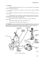
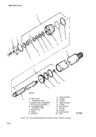
The power steering pump is a roll vane pumping element type, rated at 1.65 in.3
(27 mm³) per revolution. The pump has an internal flow control and relief valve system operating at
2000 psi (13,790 kPa) with flow rates up to 5 gal (9 Iitres) per minute (50 psi) at 3000 rpm shaft
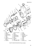
speed (fig. 16-3).
16-6. Removal.
Refer to TM 9-2320-273-20.
16-4
CAUTIO N
Back to Top

