TM-9-2320-273-34 - Page 608 of 801
TM9-2320-273-34
16-3. Installation.
a.
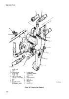
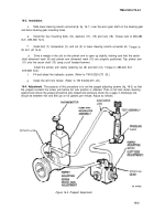
Slide lower steering column universal (6, fig. 16-1 ) over the worn gear shaft on the steering gear
and aline steering gear mounting holes.
b.
Install the four mounting bolts (14), washers (17), (15) and nuts (16). Torque nuts to 260-280
Ib-ft (353-380 N.m).
Install bolt (7), Iockwasher (3), and nut (2) in lower steering column universal (6)
35 lb-ft (47 N.m).
d.
Drive a wedge in the slot on the pitman arm to open up slightly, making sure that
shaft alinement mark (9) and pitman arm alinement mark (10) are properly positioned. Tap
(11) onto the sector shaft (13) using a soft headed hammer.
Torque to
the sector
pitman arm
Install the pitman arm clamp retaining nut (8) and bolt (12). Torque to 380-420 Ib-ft
(515-569 N.m).
f.
Fill and bleed the hydraulic system. (Refer to TM 9-2320-273 -20.)
9.
Install the left front fender. (Refer to TM 9-2320-273 -20.)
16-4. Adjustment.
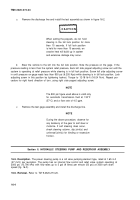
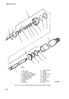
The purpose of this procedure is to set the poppet adjusting screws (fig. 16-2) so that
the poppet contacts the screw just before full lock position is attained. Then at full lock (when steering
against axle stops) the poppet should be fully tripped and pressure shown by a gage in discharge line
should be between 400 and 900 psi at 4.5 gallons per minute. Adjust as follows:
16-3
c.
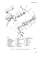
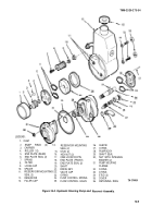
Figure 16-2. Proppett Adjustment
TA 074403
Back to Top

