TM-9-2320-273-34 - Page 613 of 801
TM9-2320-273-34
b. Cover and Bushing Assembly.
Inspect the shaft bushing for excessive burning, scoring, or oversize
condition. If any of these conditions exist, replace the cover and bushing as an assembly.
c.
Cam.
Inspect the internal surface of the cam ring for wear or scoring. Polish marks in some areas
are normal but any wear severe enough to raise a noticeable burr on the inside diameter corner of the cam
face indicates that the cam should be replaced.
d. Carrier.
Inspect the carrier on the ends and tooth drive surfaces for excessive wear or scoring. If
the ends are worn or scored, or the wear pattern On the roller drive
SU
rfa
C
e
S
i
S
greater than 3/32 in. in
width, the carrier must be replaced. If a new carrier is needed and the shaft is serviceable, replace the
carrier as follows:
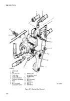
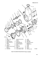
(1)
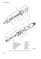
Remove the two snap rings (2) from the end of the shaft (20). Be careful not to scratch
the shaft.
(2)
Note the carrier (3) tooth orientation and then remove it from the shaft.
(3)
Install a new carrier (3) in the same orientation over the drive key (21),
(4)
Install the two snap rings (2) in the shaft grooves.
e. Shaft.
Inspect the pump shaft for excessive wear, burning, or scoring in the area of the two bushings.
If any of these conditions exist, replace the shaft. If a new shaft is needed and the carrier is okay, replace
the shaft as described in
d
above except both snaprings must be removed from the old shaft and assembled
on the new shaft.
f. Rollers.
Inspect each of the 12 rollers for burning, scoring, or wear on the outside diameter surface.
Replace any defective rollers.
g. End Plates.
Inspect both end plates for wear, cracks, or scoring on the surface opposite the
sealing rings. Any defect indicates replacement is required.
h. Control Valve.
It is difficult to visually determine if the valve is defective. If the complaint was
one of low pressure and the pumping elements show no signs of wear, the control valve may be at fault.
Check that the valve has a good fit and moves smoothly in the valve bore.
i. Seals and Gaskets.
Replace all seals and gaskets whenever the pump is disassembled.
j
Reservoir Filter.
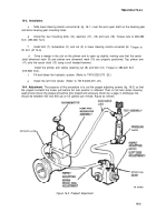
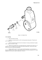
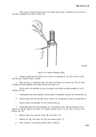
The filter (fig. 16-4) should be replaced whenever the reservoir is disassembled.
Replace as follows:
(I)
insert a screwdriver behind the filter spring and pry the spring out.
(2)
Remove the filter.
(3)
Remove the loose cap and spacer on the return tube inside the reservoir.
(4)
Clean the reservoir thoroughly.
(5)
Slide the spacer and cap over the end of the return tube.
(6)
Position the open end of the filter over the cap.
(7)
Insert the spring into the cupped, closed end of the filter and push it into position in the
neck of the reservoir.
16-8
Back to Top


