TM-9-2320-273-34 - Page 622 of 801
TM9-2320-273-34
16-18. Assembly.
a.
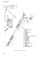
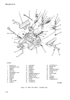
Slide ball bearing (13, figure 16-7) and sleeve spacers (11 ) and (12) onto upper steering shaft (2).
b.
Install nut (1) onto upper steering shaft (2).
c.
Bend in tang on sleeve spacer (11) to index the hole in upper steering shaft (2)
:
d.
Insert upper steering shaft (2) into upper steering column housing (10).
e.
Drive ball bearing (14) into upper steering column housing (10).
f.
Insert nut (1) and upper steering shaft (2) into a large socket to protect the horn wire.
9.
Place socket with nut (1) and upper steering shaft (2) on the floor.
h.
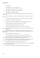
Install the sleeve spacer (15), flat washer (16), spring (17), retaining ring cage (19) and retain-
ing ring (18) to the upper steering shaft (2).
i.
Remove nut (1) from upper steering shaft (2).
16-19. Installation.
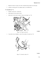
Position upper steering column in steering column clamp (22, fig. 16-7) and rubber
insulator (23), and fasten with six screws and washers (21).
b.
Connect the upper steering shaft (2) to the lower steering column U-joint. (Refer to TM 9-
2320-273-20).
Fasten horn brush (6) and terminal (9) to upper steering column housing (10) with two
screw (7) and washers (8).
d.
Install horn brush cover (5) with two screws (4) and washers (3).
e.
Install turn signal control. (Refer to TM 9-2320-273 -20.)
t
M915, M916, M917 and M920. Install the trailer hand brake valve. (Refer to TM 9-2320-
273-20.)
9.
Install steering wheel and horn button. (Refer to TM 9-2320-273 -20.)
Change 1
16-17
Back to Top

