TM-9-2320-273-34 - Page 628 of 801
TM9-2320-273-34
CHAPTER 17
REPAIR OF FIFTH WHEEL
Section I. M915
17-1. Removal.
(Refer to TM 9-2320-273 -20.)
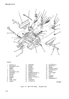
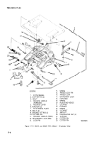
17-2. Disassembly (fig. 17-1 ).
a.
Using a hammer and knockout punch, drive out spiral pins (21, fig. 17-1).
b.
Using hammer, tap out bracket pins (20) and lift off brackets (1) from plate (23).
c.
Using rawhide hammer and wood dowel, tap out rubber bushings (19).
d.
Remove capscrew (6), washers (7) and (9), and roller (8) from hole (C) in camplate (16).
Remove locknut (18), capscrew (13), washers (14) and (17), and roller (15) from hole (B)
in camplate (16).
f.
Remove camplate (16) from release handle (29).
9.
Remove release handle (29) with spring (28) and washers (27) attached and then remove
washers (27) and spring (28) by sliding over covered end of handle (29).
h.
Using punch and hammer remove roll pin (4).
i.
Remove secondary lock (5) and spring (3).
i
Remove secondary lock handle (2).
k.
Remove yoke shank (11 ), spring (12), rubber block (36), washer (35), and locknut (34) by
pulling on shank and tapping on back of yoke (10) with hammer.
/.
Remove yoke (10).
m.
Remove cotter pins (30), pin (33), spring (31 ), and Iockguard (32).
Remove cotter pins (26) and, using a hammer and suitable drift, drive out Iockpins (24)
from bottom side of assembly.
o.
Remove lock jaws (25),
17-3. Repair or Replacement.
a.
Check to see that grease fittings (22) will take grease. Replace if necessary.
b.
Replace any component that is cracked or deformed.
17-1
e.
Back to Top

