TM-9-2320-273-34 - Page 634 of 801
TM9-2320-273-34
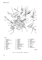
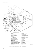
17-9. Assembly (fig.17-4).
a.
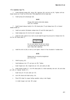
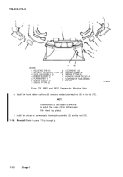
Install adjusting wedge (20), spring (19), capscrew (18), and lock nut (21). Tighten until one
thread shows out of lock nut at this time. Final adjustment will be made later.
b.
Install spring (23) and-plunger (22).
NOTE
Plunger (22) must be held while release
lever (5) is installed.
Install forward release handIe (4) in fifth wheel plate (7) and release lever (5) on forward
release handle (4).
d.
Install one washer (6) between release lever (5) and fifth wheel plate (7).
e.
Install release lever (5) into the slot in plunger (22).
f.
Install the other washer (6) on bolt (3) and install through the pivot point of release lever (5)
into the fifth wheel plate (7).
9.
h.
i.
i.
k.
Do not over tighten the bolt and locknut
in the next step as the release lever must
move freely after tightening.
Install the lock nut (24) on bolt (3) and tighten. Check for free movement of release lever.
NOTE
Release lever (4) should be straightened
out at this time.
Install
Install
U-spring (27).
stationary lock (17) and jam nut (25). Tighten.
Install hinged lock (16), hinged lock pin (15), and cotter pin (28).
Install release handle (11 ) into fifth wheel plate (7). Install secondary lock arm (12) and cotter
pin (29) on release handle (11).
.
/.
Install lock pin (13) and cotter pin (10).
m
Lock fifth wheel and install spring (14).
n.
Check fifth wheel for proper locking operation using a new kingpin.
(1) Install kingpin and lock fifth wheel.
17-7
c.
CAUTIO N
Back to Top

