TM-9-2320-280-20-2 - Page 777 of 951
TM 9-2320-280-20-2
7-62
Change 3
7-25. REAR DUAL SERVICE/PARKING BRAKE ROD REPLACEMENT
This task covers:
a. Removal
b. Installation
INITIAL SETUP:
Tools
General mechanic’s tool kit:
automotive (Appendix B, Item 1)
Materials/Parts
Three cotter pins (Appendix G, Item 12)
Locknut (Appendix G, Item 79)
Locknut (Appendix G, Item 86)
Manual References
TM 9-2320-280-10
TM 9-2320-280-24P
CAUTION
The following procedure applies to vehicles with serial numbers
USBL Eff. 44825 and above.
1.
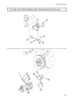
Remove two cotter pins (left and right) (23), washers (22), clevis pins (20), and brake clevis (21)
from caliper levers (24). Discard cotter pins (23).
2.
Remove clip (5) and spread boot (6) to allow access to cotter pin (12).
3.
Remove cotter pin (12), washer (11), clevis pin (8), and clevis (9) from brake rod (14) and
bellcrank (7). Discard cotter pin (12).
4.
Remove locknut (17), washer (16), spacer (15), washer (3), capscrew (4), and spring (2) from
body (13). Discard locknut (17).
5.
Remove locknut (19) and conical washer (18) from brake rod (14) and brake cable equalizer bar (1).
Discard locknut (19).
6.
Remove brake rod (14) by sliding brake rod (14) forward.
7.
Remove clevis (9) and nut (10) from brake rod (14).
1.
Install spring (2) and spacer (15) on body (13) with washer (3), capscrew (4), washer (16), and
locknut (17).
2.
Install nut (10) and clevis (9) on brake rod (14).
3.
Slide brake rod (14) rearward through spring (2).
4.
Install brake rod (14) on brake cable equalizer bar (1) with conical washer (18) and locknut (19).
Tighten locknut (19) far enough to expose 3-5 threads on the end of brake rod (14).
5.
Spread boot (6) and install clevis (9) on bellcrank (7) with clevis pin (8), washer (11), and cotter pin (12).
6.
Install clip (5) on boot (6).
CAUTION
Ensure that the caliper cable bracket is secure with no signs of
looseness and the lever is in contact with the caliper cable bracket
stop. Damage to equipment and poor performance will result if
not aligned properly.
7.
Install brake clevis (21) on rear caliper levers (24) with clevis pins (20), washers (22), and cotter
pins (23).
b. Installation
a. Removal
Equipment Condition
• Muffler and insulator removed (all models except
M1123 and “A2” vehicles) (para. 3-48).
• Muffler and catalytic converter removed (M1123
and “A2” vehicles only) (para. 3-49).
• Wheels chocked and parking brake released
(TM 9-2320-280-10).
Back to Top


