TM-9-2320-328-13-P-1 - Page 604 of 1318
TM 9-2320-328-13&P-1
0068-14
DRAFT
0068
Change 1
.
HWT0595
.
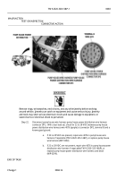
WARNING
.
ICON 3
.
Remove rings, wristwatches, neck chains, and any other jewelry before working
around vehicle.
Jewelry can catch on equipment and cause serious injury.
Jewelry
and tools may short across electrical circuits and cause damage to equipment, or
severe burns or electrical shock to personnel.
.
Step 19.
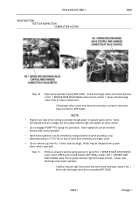
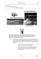
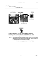
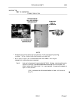
Install circuit breaker P5 (WP 0262).
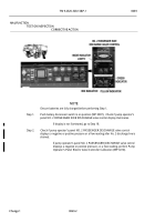
Open pump operator’s panel (WP 0207).
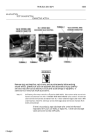
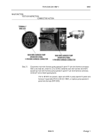
Disconnect pump house wire harness NO. 1 DRIVER SIDE DISCHARGE VALVE
control connector.
Push battery disconnect switch to on position (WP 0007).
With a
test lead set, check for 22 to 28 VDC between pump operator’s panel wire harness wire
4076 (purple) at NO. 1 DRIVER SIDE DISCHARGE valve control connector, terminal A
and a known good ground.
.
If 22 to 28 VDC are not present, go to Step 21.
.
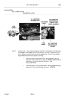
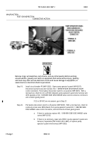
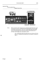
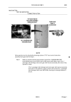
Step 20.
Pull battery disconnect switch to off position (WP 0007).
With a test lead set, check for
continuity across wire 3895 (black) from pump operator’s panel NO. 1 DRIVER SIDE
DISCHARGE valve control connector, terminal B and a known good ground.
.
a.
If there is continuity, replace NO. 1 DRIVER SIDE DISCHARGE valve
control (WP 0210).
.
b.
If there is no continuity, repair wire 3895 in pump operator’s panel wire
harness if repairable (TM 9-2320-325-14&P), or replace pump
operator’s panel wire harness (WP 0303).
.
MALFUNCTION
TEST OR INSPECTION
CORRECTIVE ACTION
Back to Top


