TM-9-2320-328-13-P-1 - Page 600 of 1318
TM 9-2320-328-13&P-1
0068-10
DRAFT
0068
Change 1
.
HWT0591A
.
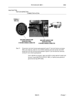
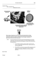
Step 14.
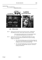
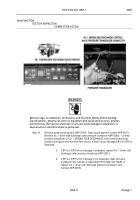
Remove 4 screws and bezel from pump operator’s panel NO. 1 DRIVER SIDE
DISCHARGE valve control.
Check for signs of water and moisture damage.
.
If valve control shows evidence of water and moisture damage, replace
NO. 1 DRIVER SIDE DISCHARGE valve control (WP 0210).
.
Step 15.
Install 4 screws and bezel on NO. 1 DRIVER SIDE DISCHARGE valve control.
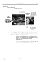
Remove No. 1 driver side discharge valve (WP 0314) and inspect it for binding,
damage, and contamination.
.
a.
If No. 1 driver side discharge valve is free from binding, damage, and
contamination, reinstall valve (WP 0314) and replace No. 1 driver side
discharge valve motor and drive assembly (WP 0248).
.
b.
If No. 1 driver side discharge valve is not free from binding, damage,
and contamination, repair (WP 0249) or replace No. 1 driver side
discharge valve (WP 0314).
.
MALFUNCTION
TEST OR INSPECTION
CORRECTIVE ACTION
Back to Top


