TM-9-2320-328-13-P-1 - Page 592 of 1318
TM 9-2320-328-13&P-1
0068-2
DRAFT
0068
Change 1
.
HWT1350A
.
NOTE
Ensure batteries are fully charged before performing Step 1.
.
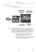
Step 1.
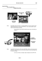
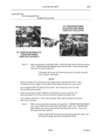
Push battery disconnect switch to on position (WP 0007).
Check if pump operator’s
panel NO. 1 DRIVER SIDE DISCHARGE valve control display illuminates.
.
If display is not illuminated, go to Step 18.
.
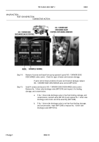
Step 2.
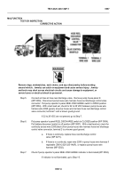
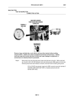
Check if pump operator’s panel NO. 1 DRIVER DISCHARGE valve control displays a
negative or positive pressure or a flow reading after NO. 1 DISCHARGE line is drained.
.
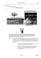
If pump operator’s panel NO. 1 DRIVER DISCHARGE valve control displays
a negative or positive pressure, or a flow reading, perform Pump Operator’s
Panel Electric Valve Controller Calibration (WP 0210).
.
MALFUNCTION
TEST OR INSPECTION
CORRECTIVE ACTION
Back to Top

