TM-9-2320-328-13-P-1 - Page 597 of 1318
TM 9-2320-328-13&P-1
0068-7
DRAFT
0068
Change 1
.
HWT0588
.
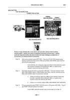
Step 10.
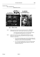
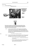
Open pump operator’s panel (WP 0207).
Check discharge valve control wire harness
at NO. 1 DRIVER SIDE DISCHARGE valve control and No. 1 driver side discharge
valve motor for loose connections.
.
If discharge valve control wire harness connectors are loose, reconnect
loose connectors (WP 0284).
.
NOTE
•
Engine may have to be running to provide enough power to operate valve control.
Valve
will operate with less voltage, but only yellow indicator light will register on valve control.
•
Do not engage PUMP PTO during this procedure.
Valve operations can be checked
without water pump operation.
•
Valve motor operation can be checked by noting vibration of valve assembly, or by
observing rotation of 7/16” hex at end of valve drive assembly worm gear shaft.
•
Do not remove cap from No. 1 driver side discharge.
Water may be released from system
when valve is operated.
.
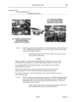
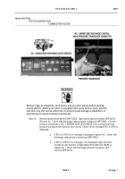
Step 11.
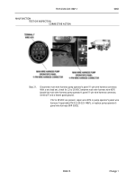
While an assistant pushes pump operator’s panel NO. 1 DRIVER SIDE DISCHARGE
valve control OPEN and CLOSE buttons (WP 0004), check if NO. 1 DRIVER SIDE
DISCHARGE valve control yellow indicator light illuminates and No. 1 driver side
discharge valve motor operates.
.
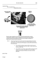
If yellow indicator light illuminates and valve motor operates, replace No. 1
driver side discharge valve drive assembly (WP 0248).
.
MALFUNCTION
TEST OR INSPECTION
CORRECTIVE ACTION
Back to Top

