TM-9-2320-328-13-P-2 - Page 187 of 1390
TM 9-2320-328-13&P-2
0123-5
DRAFT
0123
Change 1
.
.
.
.
.
.
.
.
.
.
.
.
.
.
.
.
.
.
.
.
.
.
.
.
.
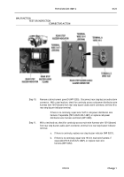
HWT3261
.
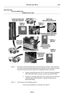
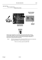
Step 5.
Pull battery disconnect switch to off position (WP 0007).
Disconnect main wire harness
driver side body wire harness connector.
With a test lead set, check for continuity
across main wire harness wire 2640 (black) from driver side body wire harness
connector, terminals D and E to a known good ground.
.
If there is no continuity at either terminal, repair wire 2640 in main wire
harness if repairable (TM 9-2320-325-14&P), or replace main wire
harness (WP 0292).
.
.
.
.
.
.
.
.
.
.
.
.
.
.
.
.
.
.
.
.
.
.
.
.
.
HWT3320
.
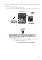
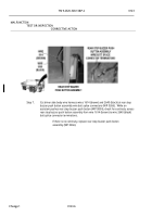
Step 6.
While an assistant pushes rear step buzzer push button (WP 0004), with a test lead set,
check for continuity between main wire harness driver side body wire harness
connector, terminals B and D, and then B and E.
.
If there is continuity between terminals B and D or B and E, repair wire 1614
in main wire harness if repairable (TM 9-2320-325-14&P), or replace main
wire harness (WP 0292).
.
MALFUNCTION
TEST OR INSPECTION
CORRECTIVE ACTION
Back to Top


