TM-9-2320-328-13-P-3 - Page 363 of 844
TM 9-2320-328-13&P-3
0380-3/(4 blank)
DRAFT
0380
6.
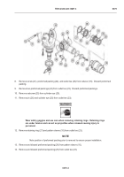
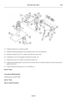
Loosen screw (15) and remove wire 1640 (16) from siren control terminal S-2 (17).
7.
Loosen screw (18) and remove wire 1052 (19) from sire control terminal S-3 (20).
8.
Loosen screw (21) and remove wire 1053 (22) from siren control terminal S-5 (23).
END OF TASK
INSTALLATION
1.
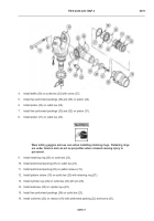
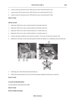
Install wire 1053 (22) on siren control terminal S-5 (23) with screw (21).
2.
Install wire 1052 (19) on siren control terminal S-3 (20) with screw (18).
3.
Install wire 1640 (16) on siren control terminal S-2 (17) with screw (15).
4.
Install wire 1637 (13) on siren control terminal S-1 (14) with screw (12).
5.
Connect cab power distribution wire harness connector (11) on siren control wire connector (10).
6.
Install siren control (8) on cab instrument panel B (9) with two washers (7), lockwashers (6) and screws (5).
7.
Install plug (3) in cab instrument panel assembly (4).
8.
Install cab instrument panel A (2) on cab instrument panel assembly (4) with seven screws (1).
END OF TASK
FOLLOW ON MAINTENANCE
Connect batteries (TM 9-2320-325-14&P)
END OF TASK
END OF WORK PACKAGE
HWT2566
Back to Top

