TM-9-2320-361-20 - Page 153 of 1207
TM 9-2320-361-20
Table 2-3. Compressed Air and Brake System Troubleshooting (Contd).
MALFUNCTION
TEST
OR INSPECTION
CORRECTIVE ACTION
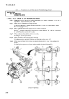
10. AIR PRESSURE DOES NOT BUILD UP TO NORMAL OPERATING PRESSURE (ABOVE 85 PSI) ACCORDING
TO GAGE
11.
Step 1. Check for compressed air leaks.
If leakage is found, repair or replace compressed air lines or fittings (TM 9-243).
Step 2. Adjust air governor (para. 8-29).
Step 3. Perform test 2 of malfunction 9.
END OF TESTING!
NOTE
Air pressure gage on instrument panel has a maximum pressure
scale of 120 psi. If old governor has been replaced with new
governor, air pressure may exceed maximum pressure reading on
instrument panel gage.
AIR PRESSURE EXCEEDS
MAXIMUM (GAGE READS OVER 120 PSI) AND SAFETY VALVE OPENS TO
RELEASE PRESSURE
Step 1.
Step 2.
Step 3.
Check for air loss through accessories (refer to malfunctions 14, 15, and 16).
NOTE
Step 2 applies to M275A2 only.
Check for excessive air pressure as indicated by instrument panel gage.
If air pressure exceeds maximum and safety valve opens to release pressure, replace air
governor (para. 8-29.
Check governor signal line (4) for crimps, bends, or leaks.
a. If governor signal line (4) is crimped, bent, or leaking, repair or replace governor signal
line (4) (para. 8-15).
b. If no restrictions are apparent, proceed to test 1.
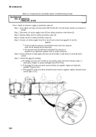
Test 1. Check governor signal line (4) pressure.
Step 1.
Step 2.
Step 3.
Step 4.
Step 5.
Step 6.
Stop engine and open all draincocks (TM 9-2320-361-10) until brake system air pressure is
vented.
Disconnect governor signal line (4) from adapter (3).
Remove adapter (3) from air governor (2).
Install tee (5) on air governor (2).
Connect test gage (1) to tee (5) and governor signal line (4) to tee (5).
Direct assistant to start engine (TM 9-2320-361-10) and allow air supply to built to normal
operating pressure.
2-68
Back to Top


