TM-9-2320-361-20 - Page 441 of 1207
TM 9-2320-361-20
4-16. SPEEDOMETER DRIVESHAFT AND ADAPTER REPLACEMENT
This task covers:
a. Speedometer Shaft Removal
c. Speedometer Adapter Installation
b. Speedometer Adapter Removal
d. Speedometer Shaft Installation
INITIAL SETUP:
APPLICABLE MODELS
EQUIPMENT CONDITION
All
Parking brake set (TM 9-2320-361-10).
Battery ground cable disconnected (para. 4-48).
REFERENCES (TM)
Front and center cab tunnels removed
LO 9-2320-209-12-1
(para. 11-22).
TM 9-2320-361-10
TM 9-2320-361-20P
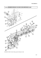
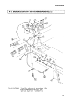
a. Speedometer Shaft Removal
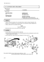
1. Turn four lockstuds
(4)
1/4 turn left and pull instrument cluster (5) away from instrument
panel (14).
2. Remove speedometer driveshaft (2) from adapter (12).
3. Remove two nuts (7), clamps (6), screws (1), and speedometer driveshaft (2) from instrument
panel (14) and floor (13).
4. Remove speedometer driveshaft (2) from speedometer (3).
b. Speedometer Adapter Removal
1. Remove adapter (12) from transfer case (11).
2. Remove adapter shaft (10), sleeve (9), and driveshaft (8) from adapter (12).
c. Speedometer Adapter Installation
1. Install driveshaft (8), sleeve (9), and adapter shaft (10) on adapter (12).
2. Install adapter (12) on transfer case (11).
1. Install speedometer driveshaft (2) on speedometer (3).
2. Install speedometer driveshaft (2) on instrument panel (14) and floor (13) with two clamps (6),
screws (1), and nuts (7).
3. Install speedometer driveshaft (2) on adapter (12).
4. Position instrument cluster (5) on instrument panel (14) and lock in place by turning four
lockstuds (4) 1/4 turn to right.
4-30
Back to Top

