TM-9-2320-361-34 - Page 205 of 764
TM 9-2320-361-34
8-2. TRANSMISSION MAINTENANCE
(Contd)
c. Installation
1.
2.
3.
4.
5.
6.
7.
8.
9.
10.
11.
12.
13.
14.
15.
8-4
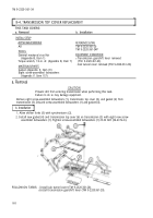
Install utility chains on transmission (6) with four washers (4) and screws (3).
Attach sling to utility chains. Attach lifting device to sling.
Position transmission (6) under vehicle and raise transmission (6).
WARNING
Use prybar to free transmission during lifting operations. Failure
to do so may result in injury to personnel or damage to
equipment.
All personnel must stand clear during lifting operations. A
swinging or shifting load may cause injury to personel .
CAUTION
Ensure transmission is alined with clutch and pilot bearing.
Failure to do so may result in damage to equipment.
Install new gasket (2) and transmission (6) on flywheel housing (1) with eleven new screw-
assembled lockwashers (11). Tighten screw-assembled lockwashers (11) 23-26 lb-ft (31-35 N.m).
Install new lockwasher (17) and ground strap (16) on transmission (6) with new screw-assembled
lockwasher (11). Tighten screw-assembled lockwasher (11)
23-26
lb-ft (31-35 N.m).
Remove lifting device from sling. Remove sling from utility chains.
Remove four screws (3), washers (4), and utility chains from transmission (6).
Install four new screw-assembled lockwashers (5) on transmission (6). Tighten screw-assembled
lockwashers (5) 25-32 lb-ft (34-43 N.m).
Aline mark on lever (14) with shaft (12) and install lever (14) on shaft (12) with screw (15)
and new
locknut (13).
NOTE
If mark does not exist on shaft or lever, position lever on spline to
rear of shaft centerline.
Push lower end of lever (14) forward until resistance is felt. Measure distance from center of hole
on
lever (14) to flange of transmission (6). Measurement should be 3.25 in. (8.26
cm). Rotate lever
(14)
one spline at a time if necessary to obtain 3.25 in. (8.26 cm) measurement. Tighten locknut (13).
NOTE
Perform step 11 if PTO is installed.
Attach power takeoff shift lever (8) on PTO arm (10) and push pin (7) in clevis (9) until
head of
pin (7) seats against clevis (9).
Install rod (23) on clutch shaft lever (18) with screw (22) and new locknut (21).
Install clevis (25) on lever (14).
Push pin (24) in clevis (25) until head of pin (24) seats against clevis (25).
Install clutch return spring (19) on clutch shaft lever (18) and frame (20).
Back to Top


