TM-9-2320-361-34 - Page 241 of 764
TM 9-2320-361-34
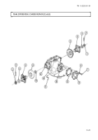
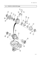
10-4. DIFFERENTIAL CARRIER REPAIR (Contd)
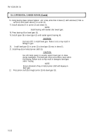
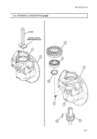
37.
38.
39.
40.
41.
42.
43.
44.
45.
46.
47.
48.
NOTE
Ensure pinion shaft is secured to prevent rotation.
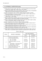
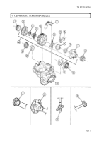
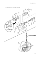
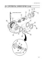
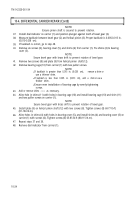
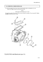
Install dial indicator on carrier (1) and position plunger against tooth of bevel gear (2).
Measure backlash between bevel gear (2) and helical pinion (3). Proper backlash is 0.005-0.015 in.
(0.013-0.038 cm).
If backlash is correct, go to step 48.
Remove six screws (6), bearing cover (5), and shims (4) from carrier (1). Tie shims (4) to bearing
cover (3).
NOTE
Secure bevel gear with brass drift to prevent rotation of bevel gear.
Remove two screws (8) and plate (9) from helical pinion
shaft (12).
Remove bearing cage (10) from carrier (1) with two puller screws.
NOTE
●
If
backlash
is
greater
than
0.015
in.
(0.038
cm),
remove a shim or
use a thinner shim.
●
If
backlash
is
less
than
0.005
in.
(0.013
cm),
add
a
shim or use a
thicker shim.
●
Ensure even installation of bearing cage by evenly tightening
screws.
Add or remove shims
(11)
as necessary.
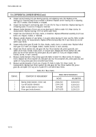
Aline hole in shims (11) with holes in bearing cage (10) and install bearing cage (10) and shim (11)
and two puller screws on carrier (1).
NOTE
Secure bevel gear with brass drift to prevent rotation of bevel gear.
Install plate (9) on helical pinion shaft (12) with two screws (8). Tighten screws (8) 60-77 lb-ft.
(81-104 N.m).
Aline holes in shims (4) with holes in bearing cover (5), and install shims (4) and bearing cover (5) on
carrier (1) with screws (6). Tighten screws (6) 65-85 lb-ft (88-115 N.m).
Repeat steps 37 and 38.
Remove dial indicator from carrier (1).
10-24
Back to Top

