TM-9-2320-361-34 - Page 597 of 764
TM9-2320-361-34
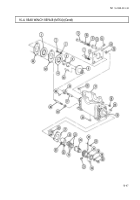
16-5. REAR WINCH REPLACEMENT (M764)
THIS TASK COVERS:
a. Removal
b. Installation
INITIAL SETUP
APPLICABLE MODELS
REFERENCES
(TM)
M764
TM 9-2320-361-20
TOOLS
TM 9-2320-361-34P
General mechanic’s tool kit
EQUIPMENT CONDITION
(Appendix B, Item 1)
Sling (Appendix B, Item 14)
●
Rear
winch
oil
drain
tubes
removed
(M764)
(TM 9-2320-361-20).
Lifting device
●
Rear winch cable removed (TM 9-2320-361-20).
MATERIALS/PARTS
.
Power divider removed (para. 16-15).
Cotter pin (Appendix F, Item 10)
●
Cab protector and mounting tubes removed
(TM 9-2320-361-20).
Six locknuts (Appendix F, Item
89)
Four locknuts (Appendix F, Item 112)
GENERAL SAFETY INSTRUCTIONS
Sixteen lockwashers (Appendix F, Item 138)
. All personnel
must stand clear during lifting
PERSONNEL REQUIRED
Two
operations.
●
Ensure lifting capacity
is
greater
than
weight
of
winch.
a. Removal
1.
Remove cotter pin (14), clevis pin (16), and winch control clevis (15) from winch lever (13). Discard
cotter pin (16).
2.
3.
4.
5.
6.
Remove six locknuts (2), screws (4), and cap (3) from body (5). Discard locknuts (2).
Remove four locknuts (18) and screws (17) from two rear winch frames (6) and subframe (8).
Discard locknuts (18).
Remove sixteen nuts (12), lockwashers (11), screws (7), washers (9), and two power divider
brackets (10) from two rear winch frames (6). Discard lockwashers (11).
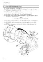
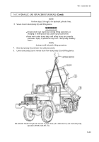
Secure chain to rear winch (1) and lifting device.
●
●
WARNING
All personnel must stand clear of winch during lifting operations.
A swinging or shifting load may cause injury to personnel.
Ensure lifting capacity is greater than the weight of winch.
Failure to do so may result in injury to personnel or damage to
equipment.
NOTE
Assistant will help with step 6.
Remove rear winch (1) from two subframes (8).
16-54
Back to Top


