TM-9-2320-361-34 - Page 641 of 764
TM 9-2320-361-34
16-21.
TRANSFER CASE POWER TAKEOFF (PTO) MAINTENANCE
THIS TASK COVERS:
a.
Removal
c. Inspection and Repair
b. Cleaning
d. Installation
INITIAL SETUP
APPLICABLE MODELS
M49A2C, M50A2, M50A3,
M756A2, and M764
TOOLS
General mechanic’s tool kit
(Appendix B, Item 1)
Torque wrench, 3/4-in. dr.
(Appendix B, Item 6)
Mechanical puller kit
(Appendix B, Item 22)
1-1/2-in. socket, 3/4-in. dr.
MATERIALS/PARTS
Six lockwashers (Appendix F, Item 147)
Gasket (Appendix F, Item 78)
Cotter pin (Appendix F, Item 6)
Two studs (Appendix F, Item 266)
Woodruff key (Appendix F, Item 296)
Sealing compound (Appendix C, Item 17)
REFERENCES (TM)
TM 9-2320-361-34P
TM 9-2520-246-34-1
TM 9-2520-246-34P
(Appendix B, Item 41)
EQUIPMENT CONDITION
Transfer case removed (para. 9-2).
a. Removal
NOTE
Perform step 1 for M756A2 vehicles.
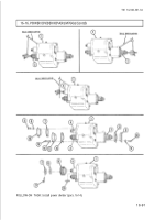
1. Remove cotter pin (9), nut (8), sprocket (21), and woodruff key (11) from power takeoff (PTO)
spindle (10). Discard cotter pin
(9)
and woodruff key (11).
2. Loosen setscrew (6) and remove cotter pin (9), nut (8), yoke (7), and woodruff key (11) from
PTO
spindle (10). Discard cotter pin (9) and woodruff key (11).
3. Disconnect line (1) from oil pump (12).
4. Remove four screws (13), lockwashers (14), two nuts (4), lockwashers (3), PTO (5), and gasket (15)
from transfer case (2). Discard lockwashers (14) and (3) and gasket (15).
5. Remove screw (19), washer (18), and clamp (17) from transfer case (2).
6. Remove line (1) and elbow (16) from transfer case (2).
b. Cleaning
Remove gasket material and debris from transfer case (2) and PTO (5) mating surface.
c. Inspection and Repair
1. Check PTO (5) and transfer case (2) mating surface for scratches, cracks, and galling. Refer to TM 9-
2520-246-34-1 if scratched, cracked, or galled.
2. Check PTO gear for wear, cracks, and discoloration. Refer to TM 9-2520-246-34-1 if gear teeth are
worn, cracked, or discolored.
3. Inspect studs (20). Replace studs (20) if damaged (para. 2-9).
16-98
Back to Top


