TM-9-2320-366-20-4 - Page 695 of 1558
TM 9-2320-366-20-4
CAUTION
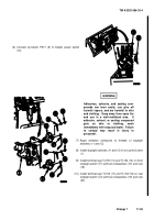
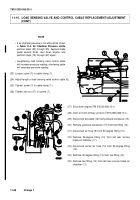
Load sensing valve control cable must be
installed in cable clamp on back side of
control lever, opposite cable clamp screw.
Failure to comply may result in damage to
load sensing valve control cable.
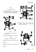
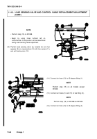
(17) Install load sensing valve control cable (17) in cable
clamp (18).
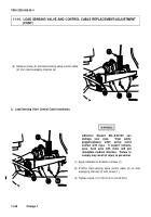
(18) Perform load sensing valve adjustment.
e. Load Sensing Valve Adjustment.
WARNING
Proper adjustment of load sensing valve
may only be accomplished with vehicle
unloaded. Failure to comply may result in
injury
to
personnel
or
damage
to
equipment.
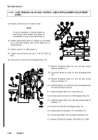
(1) Position cable clamp (1) on control lever (2) in
accordance with
Table 11-1. Load Sensing Valve
Cable Clamp Dimensions
.
NOTE
Dimensions in
Table 11-1. Load Sensing
Valve
Cable
Clamp
Dimensions
are
measured from center of pivot shaft to center
of cable clamp.
Table 11-1. Load Sensing Valve Cable Clamp Dimensions
Model Number
Dimension
M1083, M1089, M1093, M1092
6-13/16 - 7-1/16 in. (173-179 mm)
M1084, M1086
5-7/8 - 6-1/8 in. (149-155 mm)
M1085, M1088, M1090, M1094,
M1096
6-1/2 - 6-3/4 in. (165-171 mm)
Change 1
11-65
Back to Top

