TM-9-2320-366-34-3 - Page 725 of 1178
TM 9-2320-366-34-3
Change 2
16-497
16-82.
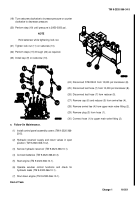
M1089 LINEAR DIRECTIONAL CONTROL VALVE REPLACEMENT/REPAIR
This task covers:
a. Removal
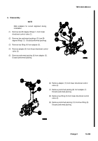
b. Disassembly
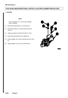
c. Assembly
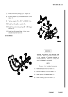
d. Installation
e. Adjustment
f. Follow-On Maintenance
INITIAL SETUP
Equipment Conditions
Batteries disconnected (TM 9-2320-366-20-3).
Hydraulic reservoir supply and returned valve closed
(TM 9-2320-366-10-2).
Control panel assembly covers removed (TM 9-
2320-366-20-5).
Selector valve removed (para 16-80).
Tools and Special Tools
Tool Kit, Genl Mech (Item 78, Appendix B)
Goggles, Industrial (Item 28, Appendix B)
Pan, Drain (Item 43, Appendix B)
Wrench, Torque, 0-175 lb-ft (Item 92, Appendix B)
Wrench Set, Crowfoot, Ratcheting (TM 9-2320-366-
20)
Tools and Special Tools Cont
Gun, Air Blow (Item 30 Appendx-B).
Materials/Parts
Nut, Self-locking (3) (Item 181, Appendix F)
Packing, Preformed (2) (Item 229, Appendix F)
Packing, Preformed (3) (Item 230, Appendix F)
Lubricating Oil, Engine (Item 45, Appendix C)
Dispenser, Pressure Sensitive Adhesive Tape (Item
30, Appendix C)
Splice (4) (Item423.1 Appendix F)
Insulation Sleeving, Electrical (Item 42.1 Appendix
C)
Personnel Required
(2)
a.
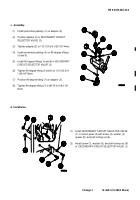
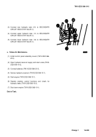
Removal.
(1)
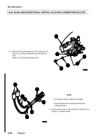
Remove two nuts (1), washers (2), and solenoids
(3) from lineal directional control valve (4).
(2) Disconnect hydraulic tubes (5 through 11) from linear
directional control valve (4).
NOTE
Tag electrical wires and connection points
prior to disconnecting.
Back to Top

