TM-9-2330-202-13-P - Page 204 of 552
REMOVAL - Continued
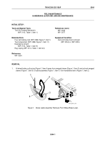
2.
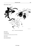
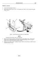
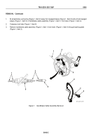
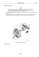
Compress lock tabs (Figure 2, Item 4).
3.
Remove cable assembly (Figure 2, Item 1) from handbrake lever (Figure 2, Item 2) through backing plate
(Figure 2, Item 3).
1
2
3
4
M116_M101_068
Figure 2.
Brake Cable Assembly Removal From Wheel Brake.
NOTE
Configuration varies. Perform Step 4 or 5 as applicable.
4.
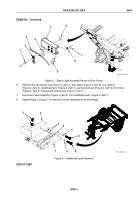
Remove two self-locking nuts (Figure 3, Item 6) and machine screws (Figure 3, Item 1), retaining strap
(Figure 3, Item 2), cable assembly (Figure 3, Item 3), and spacer plate (Figure 3, Item 4) from frame
(Figure 3, Item 5). Discard self-locking nuts (Figure 3, Item 6).
5.
Remove two nuts (Figure 3, Item 7), lockwashers (Figure 3, Item 8), and U-bolt (Figure 3, Item 9). Discard
lockwashers (Figure 3, Item 8).
TM 9-2330-202-13&P
0044
0044-2
Back to Top

