TM-9-2330-202-13-P - Page 198 of 552
REMOVAL
1.
Block and support frame securely, front and rear.
2.
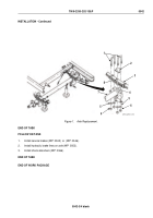
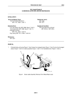
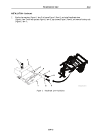
Place lifting device under midpoint of axle (Figure 1, Item 7) to provide a balanced support.
3.
At each end of axle (Figure 1, Item 7), remove four self-locking nuts (Figure 1, Item 6) and washers
(Figure 1, Item 5), two U-bolts (Figure 1, Item 1), and bumper (Figure 1, Item 2) from spring assembly
(Figure 1, Item 3) and spring plate (Figure 1, Item 4). Discard self-locking nuts (Figure 1, Item 6).
WARNING
Axle weighs over 100 lb (45 kg). Use suitable lifting device. Failure to comply may result in
death or injury to personnel. Seek medical attention in the event of an injury.
4.
Remove axle (Figure 1, Item 7) from under trailer and from lifting device.
END OF TASK
INSTALLATION
WARNING
Axle weighs over 100 lb (45 kg). Use suitable lifting device. Failure to comply may result in
death or injury to personnel. Seek medical attention in the event of an injury.
1.
Place midpoint of axle (Figure 1, Item 7) on lifting device and position axle (Figure 1, Item 7) under trailer.
2.
Raise axle (Figure 1, Item 7) until it contacts underside of spring assembly (Figure 1, Item 3). At each end of
axle (Figure 1, Item 7), engage spring assembly center bolt head (Figure 1, Item 8) with hole in pad on bumper
(Figure 1, Item 2).
3.
Install bumper (Figure 1, Item 2) on each spring assembly (Figure 1, Item 3).
4.
At each end of axle (Figure 1, Item 7), install two U-bolts (Figure 1, Item 1) into grooves of bumper
(Figure 1, Item 2) and through holes in spring plate (Figure 1, Item 4).
5.
At each end of axle (Figure 1, Item 7), install four washers (Figure 1, Item 5) and new self-locking nuts
(Figure 1, Item 6) on two U-bolts (Figure 1, Item 1).
6.
Remove lifting device from under axle (Figure 1, Item 7).
TM 9-2330-202-13&P
0042
0042-2
Back to Top

