TM-9-2330-202-13-P - Page 205 of 552
REMOVAL - Continued
1
2
3
4
5
6
7
8
9
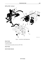
M116_M101_069
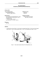
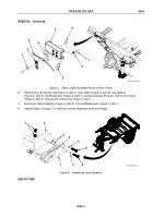
Figure 3.
Brake Cable Assembly Removal From Frame.
6.
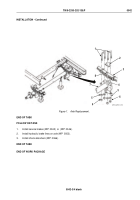
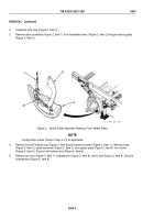
Remove two self-locking nuts (Figure 4, Item 1), cap screws (Figure 4, Item 6), and spacers
(Figure 4, Item 5), handbrake lever (Figure 4, Item 7), and two washers (Figure 4, Item 3) from frame
(Figure 4, Item 2). Discard self-locking nuts (Figure 4, Item 1).
7.
Disconnect cable assembly (Figure 4, Item 4) from handbrake lever (Figure 4, Item 7).
8.
Repeat Steps 1 through 7 for removal of other handbrake lever and linkage.
1
2
3
4
5
5
6
6
7
M116_M101_071
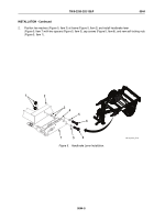
Figure 4.
Handbrake Lever Removal.
END OF TASK
TM 9-2330-202-13&P
0044
0044-3
Back to Top

