TM-9-2330-202-13-P - Page 208 of 552
INSTALLATION - Continued
CAUTION
Cable must be positioned below top spacer. To do otherwise causes cable to jump off pulley,
resulting in damage to cable. Failure to comply may result in damage to, or destruction of,
equipment or mission.
3.
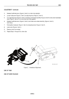
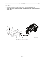
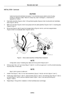
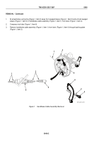
Feed cable assembly (Figure 6, Item 1) through backing plate (Figure 6, Item 4) and position at handbrake
lever (Figure 6, Item 2).
4.
Make sure lock tabs (Figure 6, Item 6) are spread and hold cable assembly (Figure 6, Item 1) in backing plate
(Figure 6, Item 4).
5.
Pull spring (Figure 6, Item 5) away from swaged sleeve (Figure 6, Item 3), and hook swaged sleeve
(Figure 6, Item 3) to handbrake lever (Figure 6, Item 4).
1
2
3
4
5
6
M116_M101_072
Figure 6.
Brake Cable Assembly to Wheel Brake Installation
NOTE
Configuration varies. If installing new cable and U-bolt, perform Steps 6 and 7.
6.
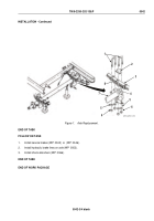
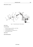
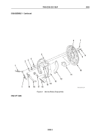
Drill two new 5/16 in (12.7 cm) holes (Figure 7, Item 9) 1 in (2.54 cm) apart and 1 in (2.54 cm) behind existing
mounting holes in frame side.
NOTE
Align U-bolt in groove of cable end.
7.
Install U-bolt (Figure 7, Item 10), two new lockwashers (Figure 7, Item 8), and nuts (Figure 7, Item 7).
8.
Install spacer plate (Figure 7, Item 4), cable assembly (Figure 7, Item 3), and retaining strap (Figure 7, Item 2)
on frame (Figure 7, Item 5) with two machine screws (Figure 7, Item 1) and new self-locking nuts
(Figure 7, Item 6).
9.
Repeat Steps 1 through 8 for installation of other handbrake lever and linkage.
TM 9-2330-202-13&P
0044
0044-6
Back to Top

