TM-9-2330-202-13-P - Page 217 of 552
CLEANING AND INSPECTION - Continued
WARNING
If one brake shoe is being replaced, replace all brake shoes on axle. The combination of old
brake shoes with new brake shoes will cause uneven braking. Failure to comply may result
in death or injury to personnel. Seek medical attention in the event of an injury.
3.
Inspect brake shoe linings for cracks or grease. Measure lining thickness. Lining thickness must be at least
1/8 in (3.18 mm). Replace brake shoes if damaged, grease soaked, or worn.
4.
Inspect strut and lever for cracks and wear. Replace if damaged.
5.
Inspect adjusting screw for corrosion or wear on teeth. Replace adjusting screw if corroded or worn.
6.
Inspect wheel cylinder for leakage and corrosion. Replace if damaged.
7.
Inspect all other removed components for cracks, breaks, distortion, corrosion, or other damage. Replace any
damaged components.
END OF TASK
ASSEMBLY
1.
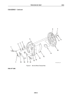
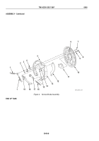
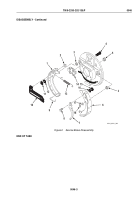
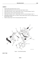
Install wheel cylinder (Figure 4, Item 11) on backing plate (Figure 4, Item 10) with new lockwasher
(Figure 4, Item 9) and bolt (Figure 4, Item 8). Torque bolt between 130 – 230 lb-in (15 – 26 N•m).
2.
Install lever (Figure 4, Item 12) on brake shoe (Figure 4, Item 13) with spring tension washer
(Figure 4, Item 14) and new clamp (Figure 4, Item 15). Pinch ends of clamp (Figure 4, Item 15) to retain it
securely in place.
3.
Install two brake shoes (Figure 4, Items 5 and 13), pins (Figure 4, Item 7), and springs (Figure 4, Item 3) on
backing plate (Figure 4, Item 10). Install two retainers (Figure 4, Item 2), spring (Figure 4, Item 19), and strut
(Figure 4, Item 18) on backing plate (Figure 4, Item 10).
4.
Turn in adjusting screw (Figure 4, Item 17) fully. Install adjusting screw (Figure 4, Item 17) and spring
(Figure 4, Item 16) between two brake shoes (Figure 4, Items 5 and 13).
5.
Install plate (Figure 4, Item 4) on anchor pin (Figure 4, Item 6).
6.
Install two springs (Figure 4, Item 1) on anchor pin (Figure 4, Item 6) and brake shoes
(Figure 4, Items 5 and 13).
TM 9-2330-202-13&P
0045
0045-7
Back to Top

