TM-9-2330-202-13-P - Page 214 of 552
DISASSEMBLY
1.
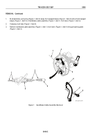
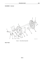
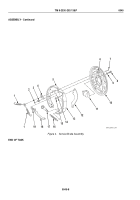
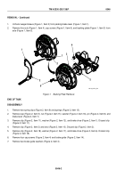
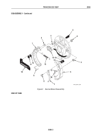
Remove two springs (Figure 3, Item 1) from two brake shoes (Figure 3, Items 5 and 13) and anchor pin
(Figure 3, Item 6). Remove plate (Figure 3, Item 4) from anchor pin (Figure 3, Item 6).
2.
Remove spring (Figure 3, Item 16) and adjusting screw (Figure 3, Item 17) from two brake shoes
(Figure 3, Items 5 and 13).
3.
Remove two retainers (Figure 3, Item 2), springs (Figure 3, Item 3), and pins (Figure 3, Item 7) from two brake
shoes (Figure 3, Items 5 and 13) and backing plate (Figure 3, Item 10).
4.
Remove two brake shoes (Figure 3, Items 5 and 13), strut (Figure 3, Item 18), and spring (Figure 3, Item 19)
from backing plate (Figure 3, Item 10).
5.
Remove clamp (Figure 3, Items 15), spring tension washer (Figure 3, Item 14), and lever (Figure 3, Item 12)
from brake shoe (Figure 3, Item 13). Discard clamp (Figure 3, Item 15).
6.
Remove bolt (Figure 3, Item 8), lockwasher (Figure 3, Item 9), and wheel cylinder (Figure 3, Item 11) from
backing plate (Figure 3, Item 10). Discard lockwasher (Figure 3, Item 9).
TM 9-2330-202-13&P
0045
0045-4
Back to Top

